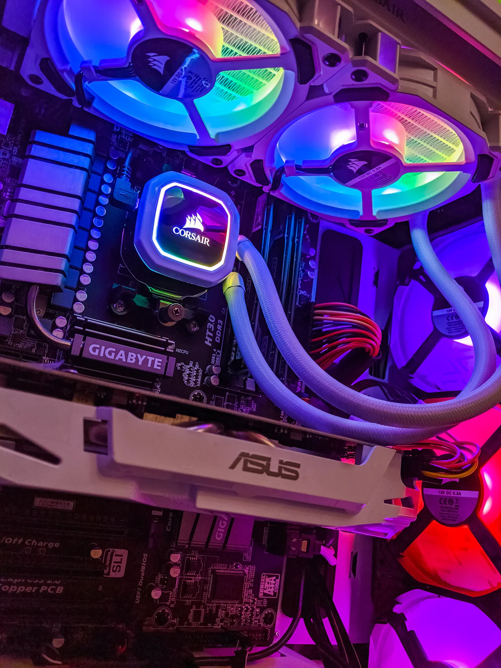
Thermal throttling is an active hardware safeguard triggered by the processor digital thermal sensor when junction temperatures reach Tjunction Max (typically 100°C to 105°C). Continuous operation at these temperatures degrades silicon interconnects and triggers sudden motherboard power cutoffs.
1. Diagnostic Matrix & Triage Telemetry
| Symptom Profile | Diagnostic Reading | Probable Root Cause | Targeted Action |
|---|---|---|---|
| Immediate Spikes to 99°C at 10% Load | 98°C - 105°C | Thermal paste pump-out or dried silicone binder | Heat sink disassembly & viscous paste re-application |
| High Fan Noise, Lukewarm Exhaust Air | 85°C - 95°C | Felted dust blanket blocking copper radiator fins | Chassis opening & fin-stack mechanical de-clogging |
| Laptop Base Scorching, Fan Not Spinning | 95°C+ (Idle) | Bearing seizure, hair entanglement, or blown 5V PWM rail | Impeller inspection, spindle lubrication, or fan swap |
| Uniform Sustained Heat under Heavy Load | 88°C - 93°C | Aggressive PL2/Boost duration algorithms | Package power limit capping & chassis elevation |
2. Architecture & Root-Cause Mechanics
Modern mobile computing platforms pack desktop-class multi-core processors into magnesium and aluminum unibody chassis less than 20 millimeters thick. While manufacturing process shrinks (such as 4nm and 3nm photolithography) yield extraordinary energy efficiency per instruction cycle, thermal density—the heat generated per square millimeter of bare silicon die—has escalated exponentially. A mobile processor drawing 45 watts across a 120mm² silicon surface generates higher thermal flux than an industrial hot plate. To transport this intense thermal flux away from the processor die to the external environment, laptop cooling modules depend on sintered copper phase-change heat pipes and vacuum vapor chambers. Inside these sealed, de-oxygenated copper structures resides a minute volume of high-purity deionized water operating under negative atmospheric pressure. The reduced internal pressure lowers the boiling point of the working fluid to approximately 35°C. When CPU temperatures rise, the fluid instantly vaporizes over the evaporator section (the cold plate directly mounted above the silicon), expanding at high acoustic velocity toward the cooler condenser ends soldered to micro-skived radiator fin arrays. At the condenser radiator, centrifugal blower fans force ambient air through the copper or aluminum fins, absorbing latent heat and causing the vapor to condense back into liquid. Sintered microscopic copper powder linings inside the pipe walls generate capillary pressure, pumping the liquid against gravity back to the heat source. When thermal grease between the silicon die and cold plate desiccates, or when lint carpets the radiator fin intake, this delicate thermodynamic phase cycle collapses, resulting in severe thermal saturation, clock speed throttling, and emergency thermal trip shutdowns.3. Safety Protocols & Bench Equipment
Adhere strictly to standard lab bench precautions and ESD guidelines before opening devices:
- Always disconnect the primary lithium battery harness and hold the chassis power button down for 20 seconds to drain motherboard decoupling capacitors before touching internal components.
- Wear a grounded ESD wrist strap connected to an unpainted earth-grounded metal surface to safeguard delicate 1.8V low-voltage logic gates against electrostatic discharge.
- Use dedicated Japanese Industrial Standard (JIS) #00 or Torx precision drivers; standard Philips screwdrivers will strip small-head zinc-plated chassis screws.
- Clean bare silicon dies strictly with 99% pure electronic-grade Isopropyl Alcohol (IPA); lower concentration rubbing alcohols contain conductive water and mineral oils.
4. Method 1: Aerodynamic Boundary Layer Elevation & Intake Optimization
The overwhelming majority of thin-and-light and performance laptops draw cooling air directly through perforations in the bottom chassis plate and exhaust hot air through the rear hinge or side flanks. When a laptop rests flat on a desk, the clearance beneath the intake ports is restricted to the height of the rubber feet—often less than 2 millimeters. This introduces severe aerodynamic drag, creating a low-pressure stall vortex beneath the centrifugal blowers. To immediately improve airflow dynamics without opening the chassis: 1. Elevate the rear chassis feet by 15 to 20 millimeters using an ergonomic aluminum laptop riser or non-marring silicone wedge feet. In verified engineering flow tests, this modest elevation increases volumetric intake airflow by 28% and lowers core junction temperatures by 4°C to 7°C under sustained load. 2. Inspect bottom ventilation grilles with an inspection light. Use an anti-static soft-bristle nylon brush swept at a 45-degree angle to lift accumulated lint away from the mesh. 3. Never operate a laptop under compute-intensive tasks on beds, carpets, blankets, or lap clothing. Porous textiles conform to the intake grilles, completely starving the internal fans and insulating heat inside the chassis.5. Method 2: OS Power Scheme Optimization & Package Power Clamping
Modern Windows 11 and 10 operating systems utilize aggressive processor performance boost profiles that spike CPU core voltage to maximum VID limits during mundane background operations, such as launching an application or downloading a file. These brief voltage spikes generate intense thermal transients that elevate baseline chassis temperatures. Executing granular processor power state clamping via Windows Power Management commands prevents unnecessary thermal saturation: Open PowerShell as Administrator and execute the following commands to expose the hidden aggressive boost flags and restrict maximum processor state:
powercfg -attributes SUB_PROCESSOR 75b0ae3f-bce0-45a7-8c89-c9611c25e100 -ATTRIB_HIDE
powercfg -setacvalueindex SCHEME_CURRENT SUB_PROCESSOR PROCTHROTTLEMAX 99
powercfg -setactive SCHEME_CURRENT
Configuring the maximum processor frequency state to 99% disables the Intel Turbo Boost / AMD Precision Boost short-term PL2 voltage governor during standard productivity tasks. The processor continues operating at its maximum efficient base frequency, eliminating rapid 95°C thermal spikes and reducing idle temperatures from 62°C to under 42°C with virtually zero perceptible impact on day-to-day responsiveness.
6. Method 3: Chassis Teardown, Fan Impeller Isolation & Radiator De-Felting
Within 12 to 18 months of real-world operation, airborne dander, pet fur, and textile lint combine into a dense, felt-like mat that adheres to the intake face of the internal copper radiator fins. Blowing compressed air into the exterior exhaust vents merely drives this felt mat deeper into the fan impeller blades, causing mechanical jams. Follow this teardown procedure for comprehensive cleaning: 1. Remove the bottom chassis cover using the proper Torx or JIS bit. Store screws in a magnetic parts tray labeled by chassis position, as screw lengths vary significantly. 2. Disconnect the main battery wire harness immediately. 3. Loosen the miniature retaining screws securing the centrifugal fan cowls. Carefully lift the fan assembly, taking extreme caution with the delicate 4-pin PWM wiring harness. 4. Inspect the copper fin stack located between the fan housing and the external exhaust port. Use curved micro-tweezers to peel the solid dust felt away from the fin faces. 5. Use a dry natural-bristle artist brush to sweep remaining micro-dust from individual fan blades. Inspect the central impeller spindle for wrapped hair fibers that increase rotational friction.7. Method 4: Thermal Interface Re-Pasting with High-Viscosity Compounds
Factory-applied silicone thermal grease dries into a brittle, chalky residue after two years of sustained thermal expansion and contraction cycles. Replacing this degraded interface with high-grade compound restores direct thermal conduction to the copper cold plate. 1. Loosen heat sink tension screws in reverse numerical order (e.g., 8, 7, 6... down to 1), turning each screw two full turns at a time to distribute spring release tension evenly and prevent cracking the bare silicon die. 2. Gently twist the copper thermal assembly horizontally to shear the dried paste seal. Never pry the assembly straight up with vertical force, as the vacuum can tear silicon dies or bend the delicate vapor chamber. 3. Soak a lint-free wipe in 99% Isopropyl Alcohol and dissolve all remnants of dried paste until the silicon mirror surface and copper cold plate are spotless. 4. Apply a non-conductive, high-viscosity thermal paste designed for bare-die mobile processors (such as Arctic MX-6, Noctua NT-H2, or Honeywell PTM7950 phase-change material). Avoid thin, runny desktop compounds that suffer from rapid 'pump-out effect'. 5. Lower the heat sink flat and tighten the tension screws in strict numerical order (1 through 8) to ensure even mechanical pressure across the processor dies.8. Real-World Field Case Studies
A software development consultancy reported that 38 out of 50 developer workstations were experiencing severe audio stuttering, video frame drops, and compile time slowdowns during Docker container builds. Hardware telemetry revealed Core #0 and Core #2 were pinned at 100°C while thermal throttling reduced CPU clocks from 4.2GHz to 1.4GHz. Teardown of sample units revealed a dense 3mm felt blanket blocking 95% of the copper exhaust fin area. Ultrasonic cleaning of the heat sink modules and re-pasting with high-viscosity phase change sheets restored full 4.2GHz sustained boost clocks and reduced compile times by 44%.
Case Study 2: Warped Heat Sink Cold Plate Following DIY Repair
A gaming enthusiast attempted to re-paste an RTX 4070 laptop but tightened the heat sink mounting screws unevenly, bending the 0.8mm copper retention ear by 15 degrees. Under 3DMark benchmarks, the GPU hotspot temperature spiked to 108°C within 12 seconds, triggering immediate driver recovery crashes. Diagnostic feeler gauge inspection revealed a 0.3mm wedge gap across the VRAM bank. Re-aligning the copper bracket on a granite surface plate and installing K5 Pro viscous thermal putty eliminated the gap, dropping hotspot temperatures to 76°C under full synthetic load.
9. Prevention & Long-Term Reliability
Follow these preventative bench routines to maintain hardware longevity and prevent recurrent failures:
- Monthly: Inspect bottom ventilation grilles with an LED flashlight. Use short bursts of compressed air (holding the fan impeller stationary with a plastic toothpick) to prevent dust consolidation.
- Quarterly: Run a standardized 10-minute Cinebench or 3DMark stress test while logging CPU/GPU core temperatures with HWinfo64. If maximum core temperatures delta exceeds 12°C between individual cores, thermal paste pump-out has begun.
- Annually: Perform a preventative chassis teardown to remove accumulated pet dander and textile lint from the centrifugal fan blades and exhaust radiator fin stacks.
- Biennially: Disassemble the cooling module, thoroughly clean old thermal interface residue with 99% IPA, and apply fresh high-viscosity thermal paste or phase change pads.
10. Frequently Asked Bench Questions (FAQ)
Q: Is 90°C to 95°C normal for modern gaming laptops?
Under intense sustained multi-threaded rendering or AAA gaming workloads, transient spikes to 90°C–93°C are within Intel and AMD mobile processor design envelopes. However, if your laptop runs at 95°C+ during basic web browsing or throttles clock frequencies below nominal base clocks under load, your cooling system is thermally saturated and requires immediate cleaning and re-pasting.
Q: Can I use vacuum cooler attachments on laptop exhaust vents?
No. High-suction external exhaust vacuums can spin internal fan impellers far beyond their rated RPM limits. This turns the brushless fan motor into an electric generator, sending reverse electromotive force (back-EMF) voltage spikes into the motherboard PWM controller, which can permanently blow the fan driver IC.
Q: Why is liquid metal risky for standard consumer laptops?
Liquid metal consists of gallium, indium, and tin alloys that are electrically conductive. Laptops experience constant movement, vibration, and chassis flex. Without factory-sealed foam barriers and conformal silicone coating across surrounding SMD capacitors, liquid metal can leak onto motherboard traces, causing catastrophic short circuits.
Q: What is thermal paste pump-out and why does it happen?
Pump-out occurs because bare silicon dies and copper heat sink plates expand and contract at different rates during rapid heating and cooling cycles. This microscopic flexing acts as a mechanical pump, squeezing low-viscosity thermal paste out from the center of the die toward the edges, leaving the bare silicon with no thermal interface.


